Thursday, January 07, 2021

pipe appurtenances

Various pipe appurtenances or fixtures are required to carry out inspections, tests, and cleaning and repairing works on isolated portions of pipes. The accessories include valves, manholes, insulation joints, anchorages, etc. that should be attached in the right position to carry out the necessary work in a pipeline system.

This article will discuss the different types of pipe appurtenances required for a functioning pipeline network:

1. Types of Valves

Valves such as sluice valves or gate valves, air valves, blow off valves, pressure relief valves, and reflux valves are required for a pipeline to function properly.

Types of Valves
Types of Valves

1.1 Sluice Valves or Gate Valves

A sluice valve or gate valve regulates the flow of water through a pipeline. They are identical to the gate valves used in dams but are comparatively smaller in size. The valve is placed at the summits (points of low pressure) of the pressure conduits. This is done so that it can be operated with ease and less force while causing minimal damage to the inner surface of the valve.

Generally, the large pipes that bring the water from the water source to the city have sluice valves placed at an interval of 3 to 5 km. This divides the entire pipeline into multiple sections and only one section is cut off while repairing by closing the end gates of the section.

1.2 Air Valves

Air valves are special valves that protect the pipeline from failing by compression caused due to vacuum. They are placed on both sides of the sluice valves, on the summits and the downstream side.

The main function of the air valve is to protect the pipe from negative pressure. When the pressure falls below a certain value in the pipe, the valve opens automatically, permitting airflow into the pipe. When the water supply is restored after repairing, the air gets accumulated at the high points and obstructs the free flow of water. Air valves help in the removal of this accumulated air.

1.3 Blow-Off Valves or Scour Valves or Drain Valves

These are small gated offtakes provided at the lower points of the pipeline to remove all the water from the pipe when the supply is closed. When this valve is opened, the water flows out of it under the influence of gravity and completely empties the pipe. Blow off valves are necessary as pipes have to be drained completely during inspection and repairs.

1.4 Pressure Relief Valves

The function of the pressure relief valves is to reduce the water hammer pressure in the pressure pipes. The valve is adjusted in such a way that it opens automatically when the pressure of the pipe exceeds a predetermined value. When the valve is opened, water flows out, and the pressure of the pipes is reduced. Once the pressure is back to normal, the valve shall close automatically.

1.5 Reflux Valves or Check Valves

These are also known as non-return valves. These valves prevent water from flowing backward i.e., in the opposite direction. They may be either provided on the pumping set’s delivery side to avoid backflow of pumped or stored water when the pump isn’t functional or to reduce the hammer force on pumps.

The reflux valves could be swing type, ball devices, flap shutter, or foot valve.

2. Manholes

To facilitate the laying of pipelines and carrying out repairs and inspections, manholes are provided at regular intervals along the pipe. It is protected by closing or grating in order to avoid mishaps or accidents. Manholes are provided mostly on RCC, steel, or Hume steel pipes that are commonly used for transmission of water and, to some extent, on cast iron pipes. On large pipelines, the manholes are provided at an approximate interval of 300 to 600 meters.

Manhole
Manhole

3. Insulation Joints

Insulating joints are also known as isolating/isolation joints. Their function is to insulate the pipeline against the flow of electric currents. The joints provide cathodic protection and thus keep electrolysis in check. Rubber gaskets or rings are provided as insulators over a specific length of the pipe or in between the length of the pipe. This provides greater resistance to the flow of current.

Insulation joints
Insulation Joints

These joints also protect the pipeline from corrosion and thus reduce maintenance efforts and related costs.

4. Anchorages

It is a basic nature of pipes to pull apart and move out of alignment at bends and points having unbalanced pressure. Unbalanced pressure causes longitudinal shear stresses and exerts an enormous force on the joints. This may loosen the joints, leading to leakage or failure of the pipes. To prevent this from happening, pipes are anchored by embedding such portions in massive concrete or masonry blocks to absorb the side thrust. Anchoring can prevent the longitudinal shear stresses from pulling the pipes apart that have been aligned on a steep slope.

Anchorage
Anchorage

Similarly, pipes are anchored when they are rigidly jointed with or without adequate provision of expansion joints. This keeps the joint from loosening up.


Monday, December 14, 2020


Types of Special Concrete


Special Concrete means the concrete used or made for special cases, such as:

Frequently, concrete may be used for some special purpose for which special properties are more important than those commonly considered. Sometimes, it may be of great importance to enhance one of the ordinary properties. These special applications often become apparent as new development using new materials or as improvements using the basic materials. Some utilize special aggregates (lightweight aggregate, steel fiber, plastic fiber, glass fiber, and special heavy aggregate).


Some special properties — increased compressive and tensile strength, water proofing, and improved chemical resistance are achieved with polymers, either as admixtures or surface treatment of hardened concrete. Admixtures for coloring concrete are available in all colors. The oldest and cheapest is perhaps carbon black. Admixtures causing expansion for use in sealing cracks or under machine bases, etc., include powdered aluminum and finely ground iron. Special admixtures are available for use where the natural aggregate is alkali reactive, to neutralize this reaction. Proprietary admixtures are available that increase the tensile strength or bond strength of concrete. They are useful for making repairs to concrete surfaces.

Uses and Applications of Special Concrete

  1. Special concrete is used in extreme weather.

  2. HPC has been used in large structures such as the Petronas Towers and the Troll Platform. Petronas Towers was the tallest concrete building in the world built in Malaysia in the mid-1990s. In 1998, the deepest offshore platform, the Troll platform, was built in Norway — a structure taller than the Eiffel Tower.

  3. Good cohesiveness or sticky in mixes with very high binder content

  4. Some delay in setting times depending on the compatibility of cement, fly ash and chemical admixture

  5. Slightly lower but sufficient early strength for most applications

  6. Comparable flexural strength and elastic modulus

  7. Better drying shrinkage and significantly lower creep

  8. Good protection to steel reinforcement in high chloride environment

  9. Excellent durability in aggressive sulphate environments

  10. Lower heat characteristics

  11. Low resistance to de-icing salt scaling

  12. PC pipes with good resistance to chemical attack from both acidic and caustic effluents inside the pipe, and from chemical attack on the outside of the pipe.


Tuesday, October 13, 2020


Types of Volcanoes & Eruptions


mt eden

Mt Eden, Auckland.

Volcanic Fields
Volcanic fields, such as Auckland and Northland, are where small eruptions occur over a wide geographic area, and are spaced over long periods of time (thousands of years). Each eruption builds a new single new volcano, which does not erupt again. Mount Eden and Rangitoto Island are examples in Auckland.

Ngauruhoe

Ngauruhoe

Cone Volcanoes
Cone volcanoes (also called composite cone or stratovolcanoes) such as Ruapehu, Taranaki / Egmont and Ngauruhoe, are characterized by a succession of small-moderate eruptions from one location. The products from the successive eruptions over thousands of years build the cones.

Lake Taupo

Lake Taupo

Caldera Volcanoes
Caldera volcanoes, such as Taupo and Okataina (which includes Mt Tarawera), have a history of infrequent but moderate-large eruptions. The caldera forming eruptions create super craters 10-25 km in diameter and deposit cubic kilometres of ash and pumice.

Types of eruptions

Multiple types of eruptions can occur at each of New Zealand’s volcanoes - the eruption type can vary minute to minute. The style of eruption depends on a number of factors, including the magma chemistry and content, temperature, viscosity (how runny the magma is), volume and how much water and gas is in it, the presence of groundwater, and the plumbing of the volcano. 

Hydrothermal eruption
An eruption driven by the heat in a hydrothermal systems. Hydrothermal eruptions pulverise surrounding rocks and can produce ash, but do not include magma. These are typically very small eruptions

Phreatic eruption
An eruption driven by the heat from magma interacting with water. The water can be from groundwater, hydrothermal systems, surface runoff, a lake or the sea. Phreatic eruptions pulverise surrounding rocks and can produce ash, but do not include new magma.

Phreatomagmatic eruption
An eruption resulting from the interaction of new magma or lava with water and can be very explosive. The water can be from groundwater, hydrothermal systems, surface runoff, a lake or the sea.

Lava
Lava is molten rock erupted at the ground surface. When molten rock is beneath the ground, it is called magma.

  • Lava flows are the effusive (non-explosive) outpourings of lava, and usually flow slower than walking pace. Lava flow types include a’a, blocky and pahoehoe.
  • Lava fountains are a fountain of runny lava fragments from a vent or line of vents (a fissure). They can form spatter piles, and if the fragments accumulate fast enough, they can form lava flows.
  • Lava domes are mounds that form when viscous lava is erupted slowly and piles up over the vent, rather than moving away as a lava flow. They are generally caused by viscous, thick, sticky lava that has lost most of its gas. They can range in volume from a few cubic metres to cubic kilometres.

Strombolian and Hawaiian eruptions
These are the least violent types of explosive eruptions. Hawaiian eruptions have fire fountains and lava flows, whereas Strombolian eruptions have explosions causing a shower of lava fragments.

Vulcanian eruptions
Vulcanian eruptions are small to moderate explosive eruptions, lasting seconds to minutes. Ash columns can be up to 20 km in height, and lava blocks and bombs may be ejected from the vent.

Subplinian and Plinian eruptions
Eruptions with a high rate of magma discharge, sustained for minutes to hours. They form a tall, convective eruption column of a mixture of gas and rock particles, and can cause wide dispersion of ash. Subplinian eruption columns are up to 20 km high, and are relatively unsteady, whereas Plinian eruptions have 20 to 35 km tall columns which may collapse to form pyroclastic density currents (PDC’s). Very rare Ultraplinian eruptions are even larger and have a higher magma discharge rate than Plinian eruptions.


Tuesday, September 22, 2020


Total station


A total station is an electronic/optical instrument used in modern surveying and building construction that uses electronic transit theodolite in conjunction with electronic distance meter (EDM).It is also integrated with microprocessor, electronic data collector and storage system.

The instrument is used to measure sloping distance of object to the instrument, horizontal angles and vertical angles. This Microprocessor unit enables for computation of data collected to further calculate the horizontal distance, coordinates of a point and reduced level of point.

Data collected from total station can be downloaded into computer/laptops for further processing of information.

Total stations are mainly used by land surveyors and civil engineers, either to record features as in topographic surveying or to set osut features (such as roads, houses or boundaries). They are also used by archaeologists to record excavations and by police, crime scene investigators, private accident Reconstructionist and insurance companies to take measurements of scenes.

total station


Wednesday, September 16, 2020


Earthquake 

Earthquake is the most dangerous natural phenomenon that generates sizable destruction in structures. It is reported that two sources of mistakes which would seriously endanger structures are ignoring the ways an earthquake affects buildings and shoddy construction practices. That is why a proper understanding of the seismic effects on a structure is extremely important, and designers and contractors should consider the influence of seismic forces on buildings in order to be able to set prevention measures against failures and collapses. As earthquake hits structures, it generates inertia forces which could be greatly destructive causing deformations and, horizontal and vertical shaking. These effects are discussed and presented below.
What are the Effects of Earthquake on Structures?

1. Inertia Forces in Structures

The generation of inertia forces in a structure is one of the seismic influences that detrimentally affect the structure. When an earthquake causes ground shaking, the base of the building would move but the roof would be at rest. However, since the walls and columns are attached to it, the roof is dragged with the base of the building.The tendency of the roof structure to remain at its original position is called inertia. The inertia forces can cause shearing of the structure which can concentrate stresses on the weak walls or joints in the structure resulting in failure or perhaps total collapse. Finally, more mass means higher inertia force that is why lighter buildings sustain the earthquake shaking better.
Fig. 1: Direction of Inertia Forces

Fig. 2: Development of Great Inertia Forces in the Six Storey of Imperial County Services Building

2. Effect of Deformations in Structures


When a building experiences earthquake and ground shaking occurs, the base of the building moves with the ground shaking. However, the roof movement would be different from that of the base of the structure. This difference in the movement creates internal forces in columns which tend to return the column to its original position.

These internal forces are termed stiffness forces. The stiffness forces would be higher as the size of columns gets higher. The stiffness force in a column is the column stiffness times the relative displacement between its ends.
Fig. 3: Lateral Force Resisting System in a House

3. Horizontal and Vertical Shaking


Earthquake causes shaking of the ground in all the three directions X, Y and Z, and the ground shakes randomly back and forth along each of these axis directions. Commonly, structures are designed to withstand vertical loads, so the vertical shaking due to earthquakes (either adds or subtracts vertical loads) is tackled through safety factors used in the design to support vertical loads.

However, horizontal shaking along X and Y directions is critical for the performance of the structure since it generates inertia forces and lateral displacement and hence adequate load transfer path shall be provided to prevent its detrimental influences on the structure.

Proper inertia force transfer path can be created through adequate design of floor slab, walls or columns, and connections between these structural elements. It is worth mentioning that the walls and columns are critical structural members in transferring the inertial forces. It is demonstrated that, masonry walls and thin reinforce concrete columns would create weak points in the inertia force transfer path.
Fig. 4: Principal Directions of a Building

Fig. 5: Load Path for Lateral Inertia Forces

4. Other Effects

Apart from the direct influences of earthquakes on a structure which are discussed above, there are other effects such as liquefaction, tsunami, and landslides. These are the indirect effects of strong earthquakes that can cause sizable destruction.

Tuesday, September 01, 2020


solid waste management process


The term solid waste management mainly refers to the complete process of collecting, treating and disposing of solid wastes.

In the waste management process, the wastes are collected from different sources and are disposed of. This process includes collection, transportation, treatment, analysis and disposal. It needs to be monitored so that strict regulations and guidelines are followed.

Sources of Solid Wastes

  • Solid domestic garbage.
  • Solid waste material from various industries.
  • Solid agricultural waste.
  • Plastics, glass, metals, e-waste, etc.
  • Medical waste.
  • Construction waste, sewage sludge

The process of waste handling and disposal varies in different countries. In India, the processes differ according to the source of solid waste. They can be classified as:

⦁ Municipal Solid Waste.
⦁ Hazardous Solid Waste.

Municipal solid waste can further be divided into biodegradable, recyclable and hazardous domestic wastes. The biodegradable waste includes rotten food, vegetable peel and mostly wet kitchen waste. Recyclable waste includes plastic and hazardous wastes include, bulb, batteries, etc.

The industry generated like chemical factories, medical waste from hospitals are considered as Hazardous Solid Waste and needs special settings to dispose of them.

In any region, solid waste management is very important for the safe disposal of wastes and to reduce environmental pollution and avoid any health hazards that it may cause.

Landfills are the most common method of disposing of solid wastes. Modern-day landfills are designed by taking care of various environmental factors and types of wastes, so as to minimize pollution and health risks.


Monday, August 31, 2020


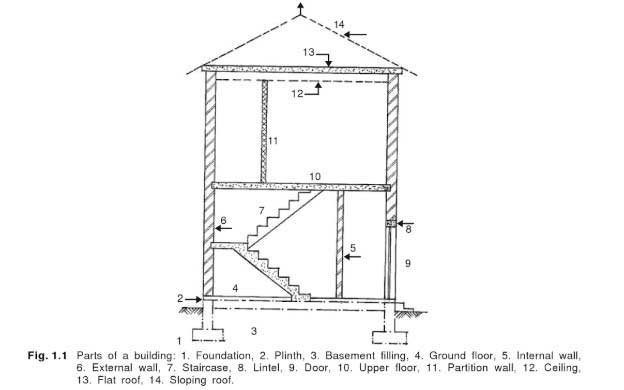
Parts of a Building


They are as follows:

1. Foundation,

2. Plinth,

3. Walls and columns,

4. Floors,

5. Lintels and chajjas,

6. Roof,

7. Doors and windows,

8. Stairs and lifts,

9. Finishing work (plastering and painting),

10. Building services,

11. Fencing and external works.,


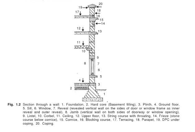
A building can be divided into substructure (foundation) and superstructure, the plinth level being the dividing line between them.


In building construction, we study how the civil works are carried out in the field after they have been planned by an architect and structurally designed by an engineer.

We should be aware that many aspects are involved in the preliminary planning and design of buildings.

For example, an architect specializes in the following works:

1. Planning the orientation, layout, and dimension of the rooms of the building

2. The preparation of the features to make the building attractive.

Work of this nature for small buildings may be taken by non-architects also.

However, the construction of a building should always be carried out under the supervision of a qualified person.

We will now briefly examine the construction of the different components of a building.
1. Foundation.

Foundation is a very important part of a building.

All the loads of superstructure are transmitted to the foundation.

A foundation engineer should know how to examine the soil profile and arrive at a suitable foundation.

The following are some of the different types of foundation generally used:

1. Strip foundation (shallow foundations)

2. Footing foundation (shallow foundations)

3. Raft foundation (shallow foundations)

4. Pile foundation (deep foundations)


5. Pier foundation (deep foundations).

In framed construction, we use footings as the foundation for the column and the brickwork for walls starts from grade beams connecting columns.

(Grade beams on under-reamed piles are also called capping beams).
Read Also: Unit Weight of Building Materials [A Complete List].
2. Plinth

The plinth is a dividing line between the substructure and superstructure.

Thus, the projecting part of the wall above the ground level to the floor level is the plinth.

The plinth is usually kept at least 45 cm (1.5 ft) above the general ground level of the building.
3. Plinth Beam.

It is capped by a beam called plinth beam.

The provision of a plinth beam and damp-proof course at plinth level are very important in building construction.
4. Damp Proof Course (D.P.C).

The damp proof course is a layer provided in building to prevent the entering of dampness from the ground to the building components.
5. Walls and Columns.

Walls are mostly made of masonry.

It may be of brick, block-work, stonework, etc.

Buildings may also be constructed as a framed structure with columns and footings and
then Walled.

Most of the flats and high-rise buildings are built this way.

In many places in the masonry, we use arches and lintels.
6.Floors.

Floor is an important part of a building.

It is the place where the inhabitants perform their most activities.

It is constructed on the filling and laid over the plinth level.

Floors are usually made from different types of materials, such as, timber, brick, R.C.C.

Top floors are nowadays usually made of reinforced concrete.
Read Also: Fineness Test of Cement; Its Apparatus, Procedure.
7. Roof.

A roof is an important part of all buildings.

The most important item in housing is to have a “roof over one’s head.”

A roof is a layer which covers the structure from the top.

It also prevents the building and inhabitants from the ill effects of the environment.

Depending on the finances available and also the climatic conditions, we can have different kinds of roofs.

Roofs can be sloped or flat.

Many types of roofs and roofing materials are available nowadays.
Watch the video below for better understanding.


8. Fabrication of Doors and Windows.

Openings are necessary in buildings for passages inside and outside the buildings.

We also need windows for lighting and ventilation.

A detailed study of doors and windows is an important part of building construction as the expenditure on this item alone can go up to 15 to 20 percent of the total cost of civil works.

Traditionally, doors and windows were made of wood and hence, this work is sometimes referred to as woodwork in buildings.

Other woodworks like provision of cupboards are also important, but it comes under the subject of interior decoration.
Read Also: Construction Specifications; Its Types, Importance.
9. Stairs and Lifts.

Nowadays most buildings are made more than one storey high.

Which means there should be a way to go from one storey of the building to another.

Knowledge of various elements of a staircase and the construction of a simple staircase is essential to all those involved in building construction.

Study of the layout and design of ornamental staircases is a special subject.

Usually, vertical transportation devices like electric lifts are to be provided in buildings having more than four floors including the ground floor.

We must also be familiar with these devices.
10. Building Finishes.

The final appearance of a building depends very much on its finishing.

We have to deal with the following:

1. Plastering and pointing

2. Painting of walls, woodwork, grillwork, etc.

It is essential that we have a knowledge of the finishing to be used on the various materials of construction such as plaster, wood, metals, etc.
11. Building Services.

Water supply, drainage, sanitation, electric supply lifts, external works, construction of cupboard, etc. are considered as items outside of civil works and are called building services.
Water supply, drainage, and sanitation (building service).

These works are considered separate from civil works and are also estimated separately.

Design and details of these will be studied in public health engineering under building services.

However, an elementary treatment of the subject is always included in basic building construction.

Wednesday, August 12, 2020


Fluid and its type

Fluids undergo continuous deformation, i.e. fluids always keep flowing. To define fluid, it is a substance that does not possess a definite shape and easily yields to external pressure. Fluid is any liquid or gas or any material that is unable to withstand a shearing or tangential force, when at rest. When the said forces are applied to the fluid, it goes through a continuous change in shape. Fluids are substances with zero shear modulus, i.e they cannot resist the shear force applied to them.

In our day-to-today life, we would have heard the dehydrated patient advised to consume more fluids to compensate for the water loss. Fluids help in the digestion of food, hence we need to take more fluids.

Classification of Fluids

Fluids are classified into four types depending on its flow, they are:Steady or unsteady
Compressible or incompressible
Viscous or non-viscous
Rotational or irrotational

Steady fluid: It is the fluid whose density remains constant at each and every point while flowing.

Unsteady fluid: It is the fluid whose velocity differs between any two points while flowing.

Compressible fluid and incompressible fluids: These are classified based on the mach number. The incompressible fluid has mach number<0.3 and the compressible fluid has mach number between 0.3 and 1.

Viscous or Non-viscous

Fluids with more thickness or viscosity are known as viscous fluids, they are generally very gloppy fluids. Examples: shampoo and motor oil.

Fluids with comparatively less thickness or viscosity are known as non-viscous fluids. These are the fluids with no resistance or negligible resistance to internal friction. Non-viscous fluids flow without any loss of kinetic energy.

Example: Superfluid liquid helium


Sunday, August 09, 2020


SOIL FORMATION 

                                            by Mr.Bright Brabin Winsley J


Soils differ from one part of the world to another, even from one part of a backyard to another. They differ because of where and how they formed. Climate, organisms, relief (landscape), parent material and time are five major factors of interaction creating different types of soils.

Climate: Temperature and moisture influence the speed of chemical reactions, which in turn help control how fast rocks weather and dead organisms decompose. Soils develop faster in warm, moist climates and slowest in cold or arid ones.

Rainfall is a part of climate
Rainfall is one of the most important climate factors in soil formation.

Organisms: Plants root, animals burrow, and bacteria eat – these and other organisms speed up the breakdown of large soil particles into smaller ones. For instance, roots produce carbon dioxide that mixes with water and forms an acid that wears away rock.

Termites can radically change a landscape.
Termites can generate mounds in the soil that are three stories tall!!!

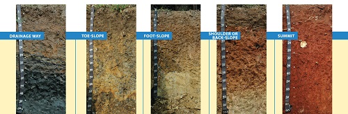
Relief (landscape): The shape of the land and the direction it faces make a difference in how much sunlight the soils gets and how much water it keeps. Deeper soils form at the bottom of a hill because gravity and water move soil particles down the slope.

Soil is different depending on where on a slope it is taken
Soils are different depending on the location in the slope that they are located.

Parent material: Every soil “inherits” traits from the parent material from which it formed. For example, soils that form from limestone are rich in calcium and soils that form from materials at the bottom of lakes are high in clay. Every soil formed from parent material deposited at the Earth's surface. The material could have been bedrock that weathered in place or smaller materials carried by flooding rivers, moving glaciers, or blowing winds. Parent material is changed through biological, chemical and environmental processes, such as weathering and erosion.

Soil forming at a volcano in real time
These are soils forming in real time from the side of the volcano. They form into rock first, then weather into fertile soil.

Time: All of these factors work together over time. Older soils differ from younger soils because they have had longer to develop. As soil ages, it starts to look different from its parent material. That is because soil is dynamic. Its components—minerals, water, air, organic matter, and organisms—constantly change. Components are added and lost. Some move from place to place within the soil. And some components are totally changed, or transformed.


Monday, August 03, 2020


       Smart Building by Abishek G L


Buildings of the future are designed to make human lives easier with the help of complex, smart technology.

Often described as smart buildings or intelligent buildings, buildings of the future are any structures that use integrated processes, smart engineering or creative design to self-regulate the building’s environment and operations.

A human-centred approach to design is at the core of buildings of the future. From the moment people step inside until the moment they leave, a building of the future will have the capability to determine the percentage of the workforce inside the building at any given time and automatically adjust the settings of its facilities according to their feedback and needs – from WiFi connections, lighting, electricity, heat, ventilation and air conditioning, buildings of the future place people at the centre.

Although they are often described as intelligent or smart, buildings of the future are not simply about the use of integrated technology to create reactive environments – they are about people, and how people will use these structures now and in the future.


Wednesday, March 11, 2020


TOTAL STATION

A total station is an optical instrument commonly used in construction, surveying and civil engineering. It is useful for measuring horizontal angles, vertical angles and distance — it does this by analyzing the slope between itself and a specific point. A high-quality total station camera combines surveying, imaging and high-speed 3D scanning into one precise and reliable instrument. It blends the latest field technologies with advanced technical features to create a tool that is trusty and dependable in demanding field situations while producing accurate results for analysis and engineering.


·        Total stations often contain a few different components:

·        Electronic transit theodolite

·        Electronic distance meter (EDM)

·        Microprocessor

·        Electronic data collector and storage system

·        Operators often use total stations with additional equipment as well, including tripods, tribrachs, reflector poles and prisms.


Using total stations for measurements provides several unique advantages:

Accuracy: How accurate is a total station? Total stations are highly accurate — to a fraction of an arc second as well as measure distances to hundredths of a foot over thousands of feet.

Ease of use: Total stations are easy and intuitive to use. They can take simultaneous distance and horizontal measurements, and they make it easy to calculate coordinates. So, operators can spend more of their time and energy on critical engineering and analytical problems that demand their attention.

Speed: Total stations collect information quickly, so operators can get in and out of the field efficiently.

Convenience: Total stations offer quick and convenient setup. With a total station, an operator can take multiple surveys from one location.

Effortless CAD interface: It’s easy to download survey data to a computer-assisted drawing (CAD) program to avoid time-consuming data manipulation.

What Are the Types and Features of Total Stations?

How many types of total stations are there? There are a few different types of total stations, each with unique features for use in various applications.

Mechanical total stations: Mechanical total stations are reliable and accurate, and they make surveying quick and easy. They do not offer remote control operation or automated features, however, and operation typically requires two people.

Robotic total stations: These total stations allow for more technological convenience. They offer extended remote control abilities, they need only one operator, and they allow for increased safety in challenging terrain because of their unique ability to operate at a distance.

Prism total stations: Both mechanical and robotic total stations come in prism models. Prism models are more traditional than reflector-less models, and they are still more commonly used. They use prisms to reflect infrared waves and then determine angles and distance by measuring the prism’s location.

Reflector-less total stations: Both mechanical and robotic total stations come in reflector-less versions, as well. These newer models of total stations are useful for taking measurements in challenging circumstances. They can work in difficult terrain or in places you can’t reach on foot, and they don’t require the use of a prism.

So, what are the features of a total station? Total stations also offer many different features to enhance their usefulness in different applications, such as:

·        Superior EDM for high accuracy and long-range prism measurements.

·        High-accuracy scanning and scanning range technology.

·        High-resolution site imagery technology.

·        Imaging solutions like video robotic control and photogrammetric measurements.

·        Integrated surveying with global navigation satellite system (GNSS) receivers.

·        Seamless field-to-office integration with software for data processing, analysis and use.

·        Optional solutions for locating lost or stolen equipment.


How Are Total Stations Used?

How is a total station camera used on the job site? Surveyors and civil engineers can use total stations to assess topography, record existing natural features, or plan for buildings, roads and land boundaries. These impressive and accurate instruments are also useful in mining, meteorology, archaeological digs, forensic investigations and building information modeling (BIM).

Total stations are particularly useful for performing functions like these:


·        Topographic surveys

·        Land and title surveys

·        Roadway and corridor surveys

·        Design surveys

·        Infrastructure surveys

·        Volumetric surveys to measure stockpile volumes

·        Power line inspections

·        Utility design surveys

·        Crash scene investigations

·        Crime scene investigations

·        Mine and quarry surveys

·        Tank calibration or inspection


\

Tuesday, February 04, 2020


Sway and non-sway in frames

A frame is considered to be non-sway (braced) if it is sufficiently braced by lateral bracing elements like structural walls. On the other hand, frames that provide lateral resistance only through columns are considered to be sway frames (unbraced). ACI 318-19 can be used as a reference to distinguish between sway and non-sway frames. It should be noted that purely sway and non-sway frames rarely exist in practice, hence, the design should be prepared based on the requirements. For instance, the designer should decide in advance if the bracing provided by shear walls, elevators, utility shafts, stairwells, or other elements would be sufficient to limit the structure against significant sway effects. It is possible that a particular storey in a structure could be sway while another is non-sway.


Sunday, January 05, 2020

 CANAL IRRIGATION

A canal is an artificial channel that is constructed to carry water to the fields to perform irrigation. The water is taken either from the river, tank or reservoirs. The canals can be constructed either by means of concrete, stone, brick or any sort of flexible membrane which solves the durability issues like seepage and erosion. The distribution system in a canal irrigation system, canal alignment, curves and certain features of canal irrigation are briefly explained in this article. 

Distribution System for Canal Irrigation System

The figure-1 below shows the general layout of a canal distribution system depicting the different networks of canals constituting a canal irrigation system. Whatever be the irrigation scheme i.e direct irrigation using weir or a barrage and storage irrigation scheme like dams or reservoir, both demand a network of irrigation canals of various sizes and capacities. Hence the canal system comprises of:

  1. Main Canal
  2. Branch Canal
  3. Distributaries or major distributaries
  4. Minors or minor distributaries
  5. Watercourses


Canal Alignment

The canal alignment is selected based on the following considerations:

  1. Canal alignment must be chosen such that the maximum area is served with the least length. It also must minimize the use of cross-drainage works.
  2. If the length of the canal is short, there is less head loss, seepage loss, and evaporation loss. This also brings additional areas for irrigation.
  3. Following a straight alignment helps to reduce the loss.
  4. Always a canal alignment with less cross-drainage work must be chosen.
  5. The canal must not pass through forest, town, village or costly areas reducing the chance of giving heavy compensation.
  6. Among different canals, ridge canals help to irrigate either side of the canal.
  7. It must help reduce heavy cutting and filling i.e costly embankment construction must be avoided.
  8. It is recommended to attain a balance in depth of cutting and depth of filling.
  9. The selection of alignment over brackish, rocky or cracked strata must be avoided.

Curves in Canals

It is always recommended to align the canals without curves. Curves result in disturbance of flow. This scours the outer side of the canals and results in silting in the inner curves.In order to avoid, scouring in the concave side, it is required to provided pitching. The canal curves must be more gentle and posses more radius in order to take large discharges.

Advantages of Canal Irrigation

The main advantages of canal irrigation are:

  1. Development of un-irrigated wasteland.
  2. Dangerous droughts can be avoided that expedite economic development.
  3. The water requirement of crops during fluctuation in rainfall intensity can be met by having a proper irrigation system.
  4. Compared to conventional watering, higher productivity per hectare land is obtained due to canals.
  5. The canals constructed are permanent that require regular maintenance.
  6. Canal irrigation does not let the water table level go down. It only helps to increase the water level thus facilitating the digging of wells.
  7. Canals also serve the purpose of hydroelectricity, drinking water supply, fishery development, and navigation.

Disadvantages of Canal Irrigation

The major disadvantages of canal irrigation are:

  1. Any imbalance in the water distribution process results in a scarcity of water in some areas and water clogging in other areas. This hence makes the soil unproductive due to the movement of harmful underground salts and alkalies to the surface level.
  2. Water present stationary in the canal results in the growth of worms, mosquitoes, and insects.
  3. Improper maintenance results in the collection of sediments in the canals that in turn affects the capacity of the canal.
  4. Canal construction demands economic investment and time. Hence, this is not a solution for all irrigation.


pipe appurtenances Various pipe appurtenances or fixtures are required to carry out inspections, tests, and cleaning and repairing works on ...